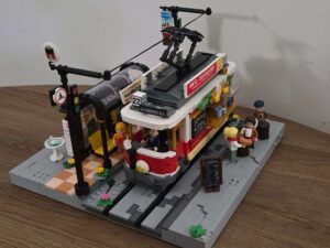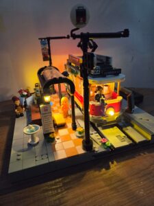

In my review of the Heritage Tram, I praised its aesthetics, but I knew that to truly integrate it into my city, it needed an upgrade.
Out of the box, the set relies on two separate battery packs – one for the station and one for the tram itself. For a temporary display, that is fine. But for a permanent city layout where I want the lights running 24/7, I needed a cleaner solution.
The Goal: Get the set onto a standard MILS plate and wire everything, including the tram, to run off a single USB power source.
A Quick Disclaimer: Read This First
This is not a precise, stud-by-stud instruction manual. This is a log of how I solved the problem using the parts and tools I had on hand.
Your build will likely look different depending on:
- Your Parts Collection: I used a random mix of LEGO and GoBricks spares from my bins. You can use whatever colours or bricks you have available. I do have an article on how to get your hands on loose GoBrick parts.
- Your Lighting Kit: I used a specific BriksMax kit because it was on sale. You might find it easier to buy individual wireless connectors or a different DIY pack.
- Your City Layout: I use MILS plates. If you use the standard out of the box Lumibricks build with no base modifications, you will need to adapt the height and wiring to match.
- Experience Recommended: This is an intermediate modification. You should be comfortable taking built sets apart, rerouting delicate wires, and using “trial and error” to make things fit. If this is your very first time modifying a set, take it slow!
Think of this guide as a blueprint for ideas, not a rigid set of rules. Adapt these techniques to fit your own city!
In this guide, I will show you how to:
- MILS Plate the set to integrate it perfectly into a city layout.
- Add Wireless Connectors to the base so it draws power from your street.
- Mod the Tram itself to pull power from the track, eliminating the battery box entirely.
The Goal
We want a sturdy, modular street section where power flows invisibly from the city into the station, and even into the vehicle itself. No dangling wires and no changing batteries.
Parts You Will Need
- 1x 32×32 Baseplate: (I use “Lekebaby” plates from Amazon, but any standard brand works).
- Spare Bricks & Plates: For the MILS structure (LEGO or GoBricks).
- Tiles: For the pavement (Light/Medium Grey).
- Wireless Power Components:
- I used parts from a Lightailing / BriksMax kit. Specifically, I bought the BriksMax lighting kit for the LEGO Tudor Corner. Link here
- Why this kit? It was on sale (~$35), and it includes a large amount of wireless connectors, expansion boards, and extension cables.
- Crucial Tip: Ensure you get BriksMax 2.0 components (the newer magnetic standard). This allows the power connection to be placed either way around.
- Shopping Hack: Most lighting kits include a photo showing the full package contents. It pays to browse around different kits to see which one offers the highest quantity of the specific parts you need (like wireless plates) for the best price.
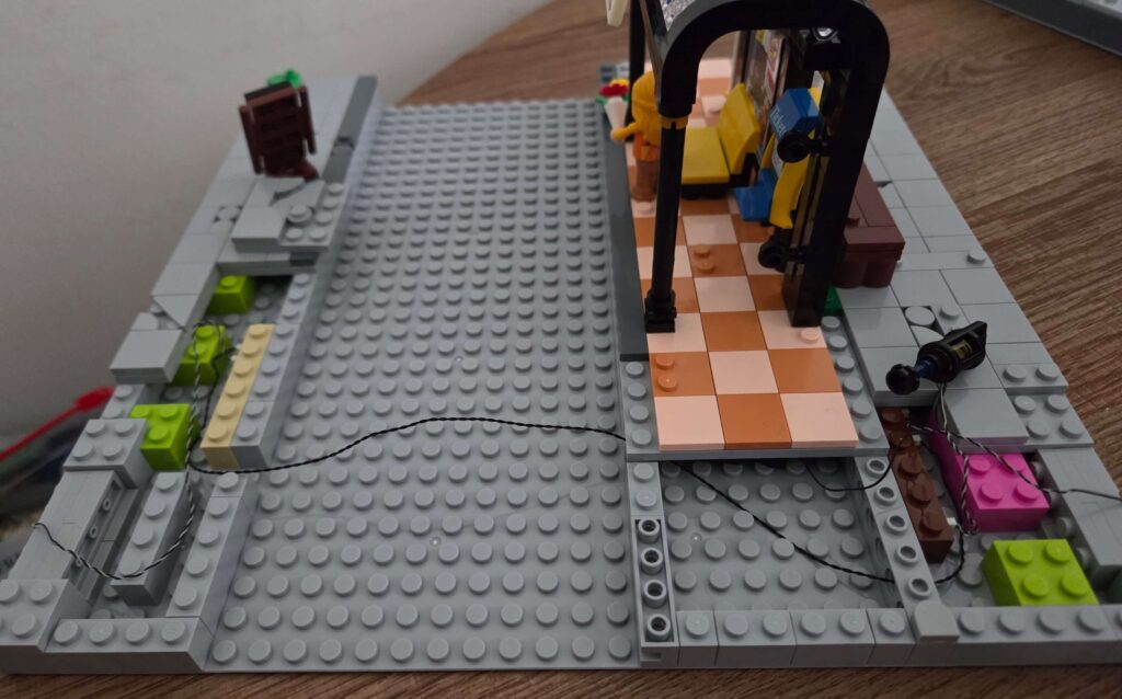
Phase 1: MILS Plating the Base (The Easy Part)
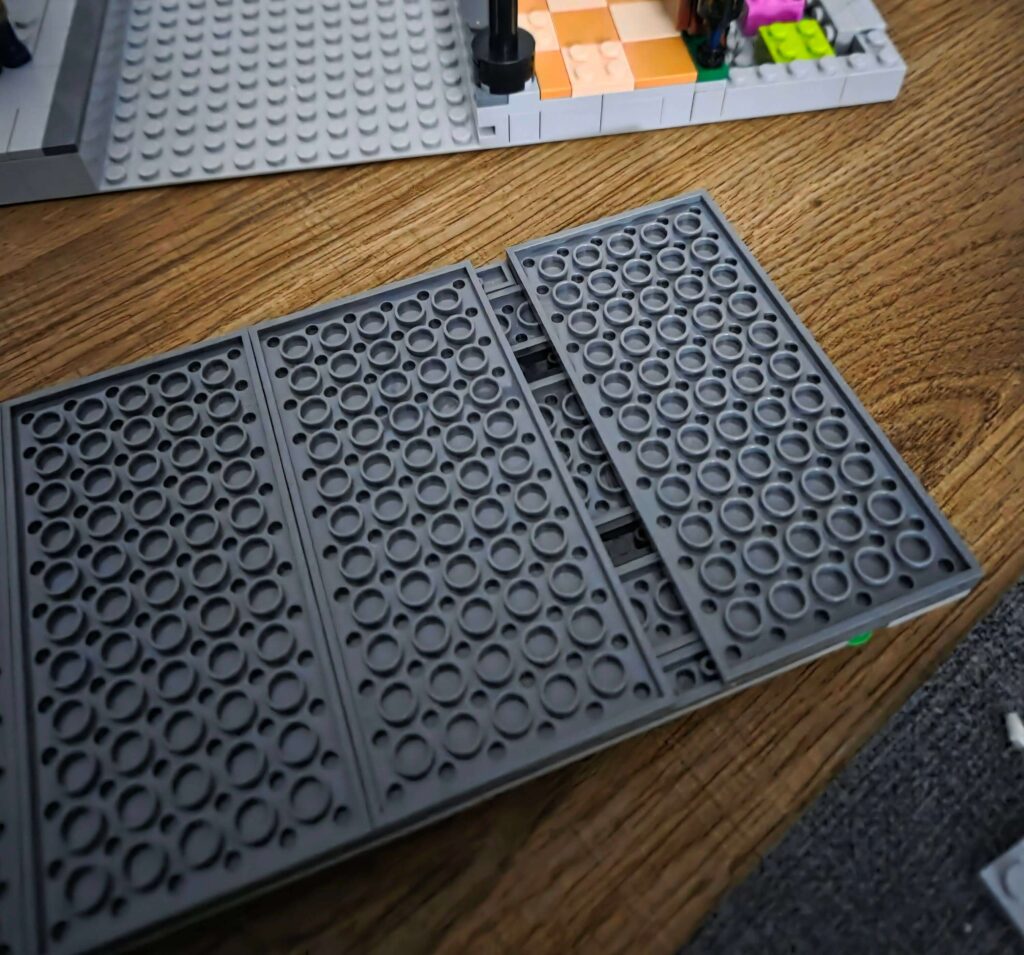
What is MILS? Modular Integrated Landscaping System. Essentially, we are putting the baseplate on a “box” of bricks to create a hollow space underneath. This allows us to run lighting cables under the pavement rather than squeezing them between bricks.
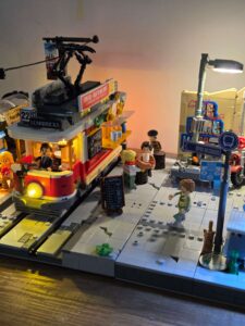
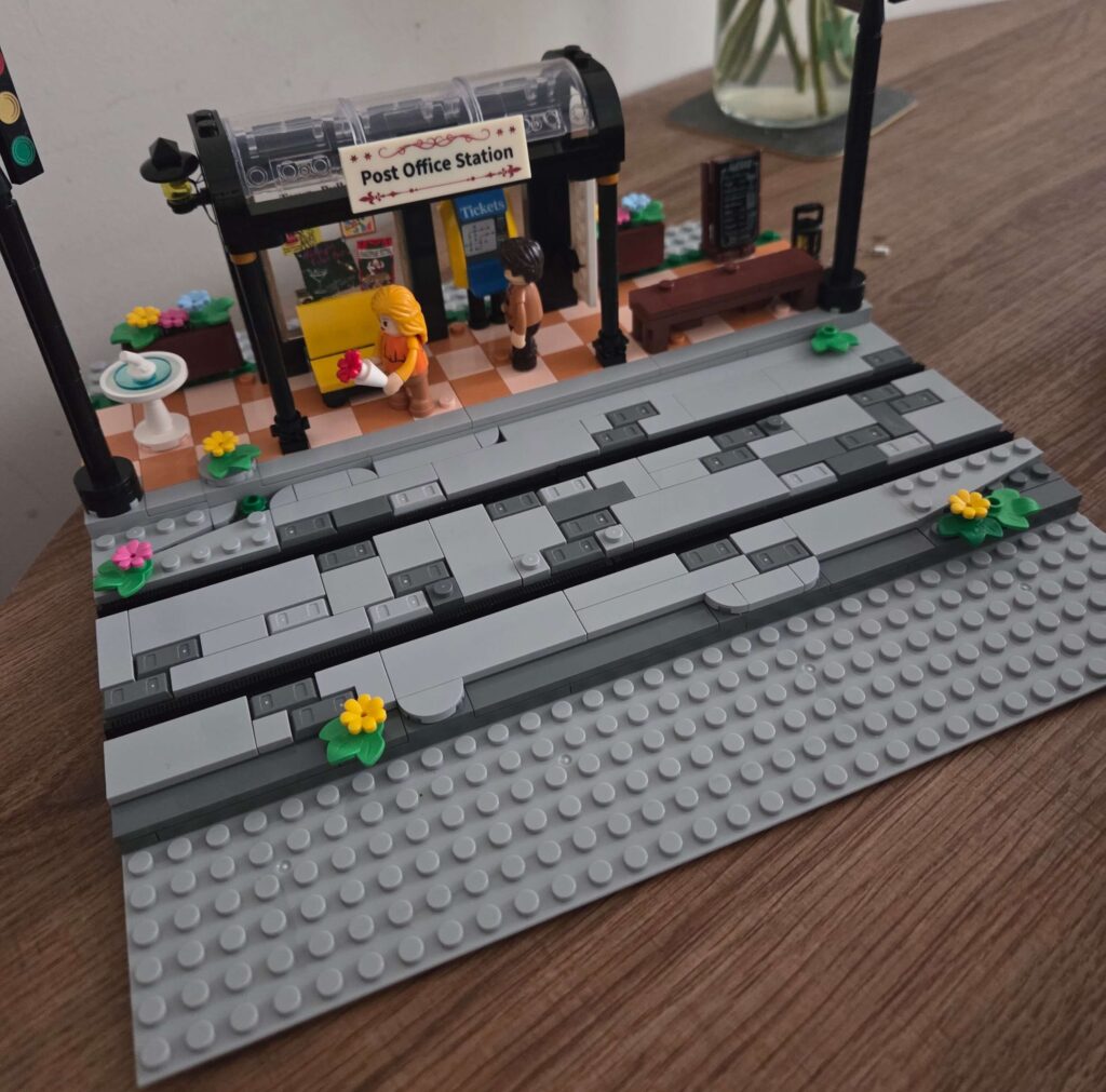
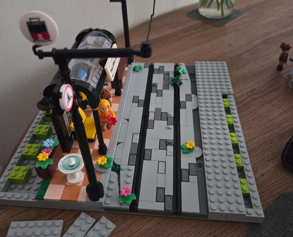
The Build: I centred the main Tram set onto a standard 32×32 baseplate. Since the original set is narrower than 32 studs, this leaves us with about 6 studs of extra space on each side.
This is actually a huge benefit. It creates wider pavements (sidewalks) and gives us breathing room to place accessories, like the water fountain, without blocking the station entrance.
Step-by-Step:
1. The Platform: First, unplug and remove the battery pack from the underside of the station. Take the loose power cable and thread it through one of the technic holes in the bricks so it hangs out the back of the platform.
Next, remove the layer of tiles from the outer edges of the platform base.
Finally, secure the modified platform onto your baseplate, ensuring you leave a 6-stud gap on the side for the pavement.
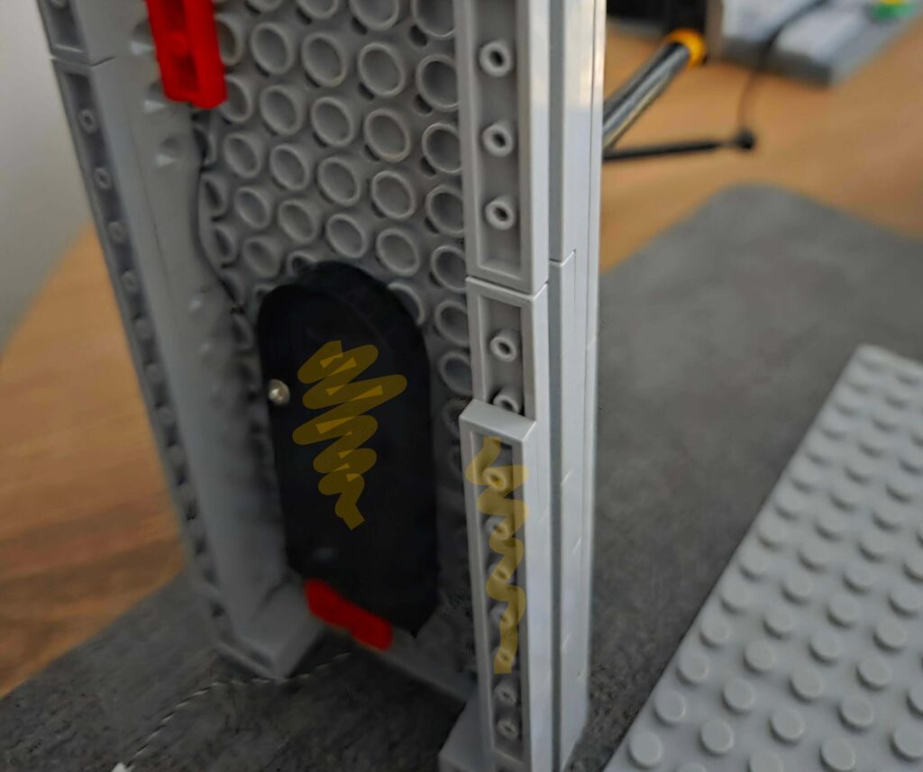
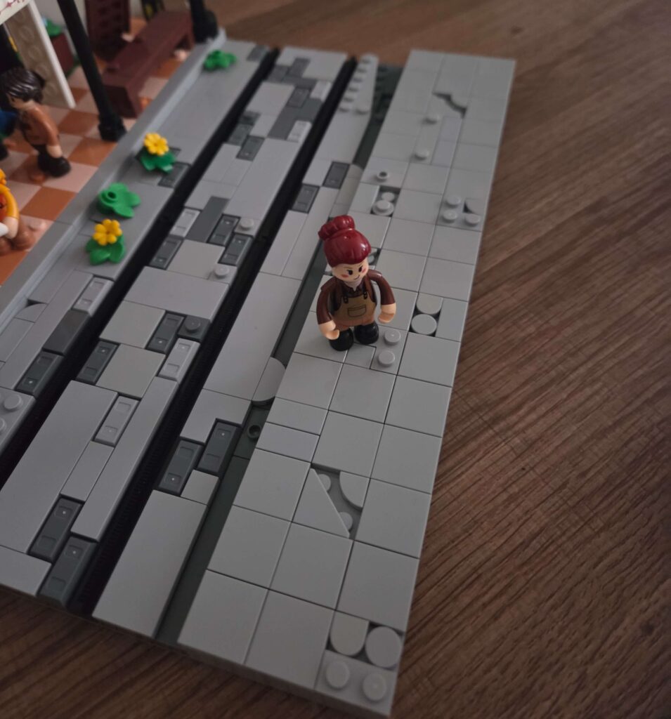
2. The Track Base: Next, remove the sliding connection plates from the side of the track base (the ones that originally locked it into the platform). Since we are mounting everything to a solid baseplate, we don’t need this locking mechanism anymore.
Strip the base down until you have just a single bottom layer of plates with the tiles and rails sitting on top. It should look like the photo below.
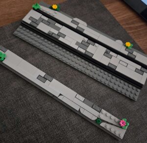
Once prepped, secure this track section onto the baseplate directly next to the platform.
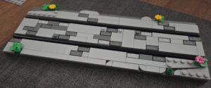
3. Building the Pavements (Sidewalks): With the main structures secured, you will have empty space on the sides.
The Structure: I used standard 2×2 bricks to build the internal support pillars. Unlike some builders who leave the sides open, I prefer to create a solid perimeter wall. This gives the base a clean, finished look, ensuring it still looks great even if I decide to display it as a standalone piece.
The Battery: Place the battery pack you removed earlier into the hollow MILS layer under the pavement. Note: You will need to unplug the cable to thread it through the side bricks so it can reach the platform/track.
The Surface: Cover the top with spare plates (I used a mix of Lumibricks spares and LEGO plates).
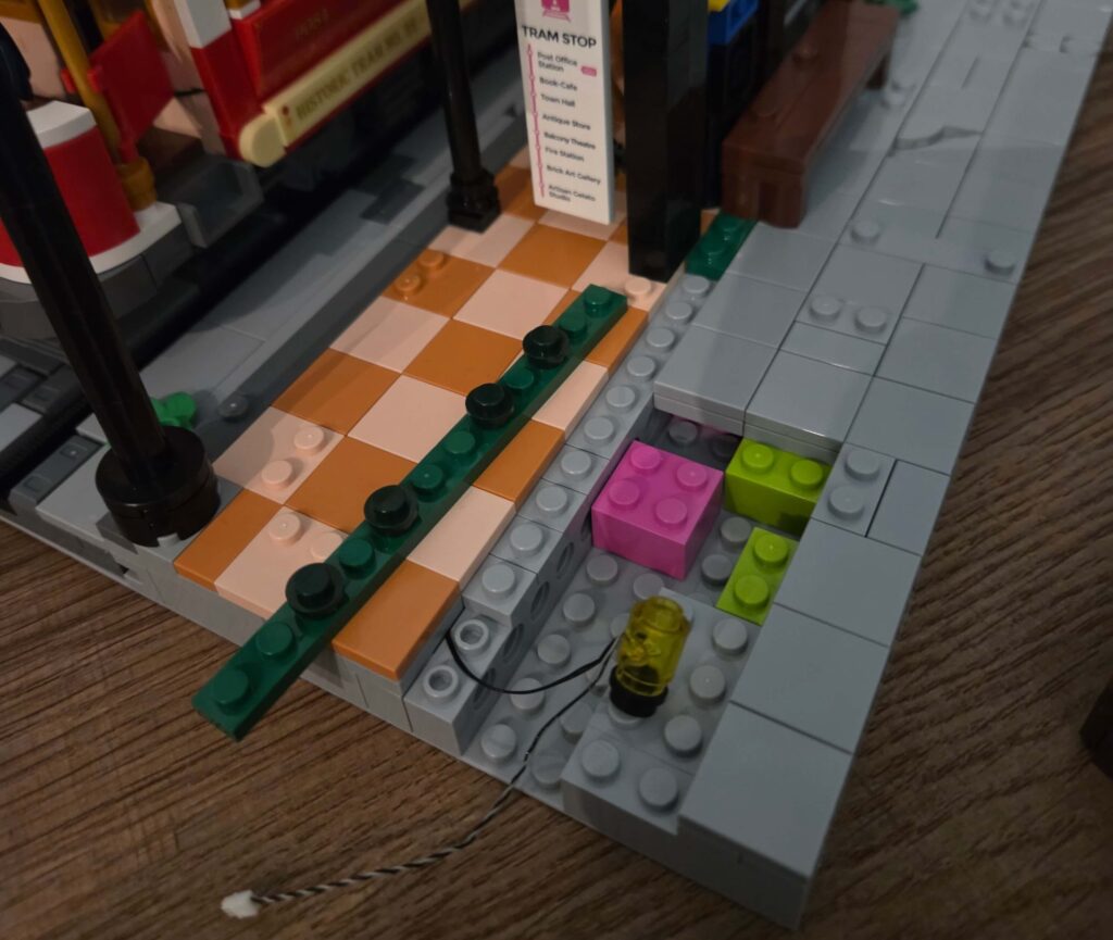
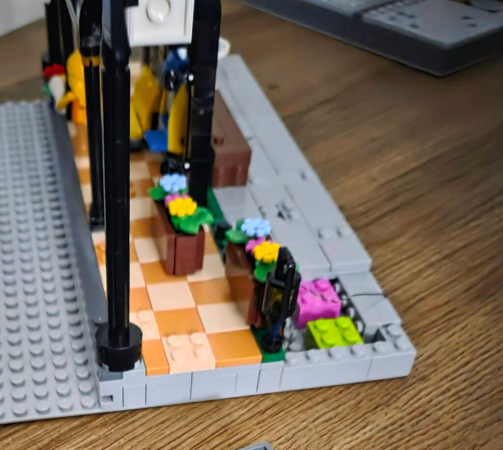
The Paving: Tile it off with Medium Grey 2×2 tiles. To give it an “Old Town” vibe, I created some broken slabs using 1×1 curved tiles and triangle tiles to break up the uniform grid.
At this point, you have a solid, nice-looking 32×32 module. But now, we need to power it.
Phase 2: Connecting the Street (The Wireless Mod)
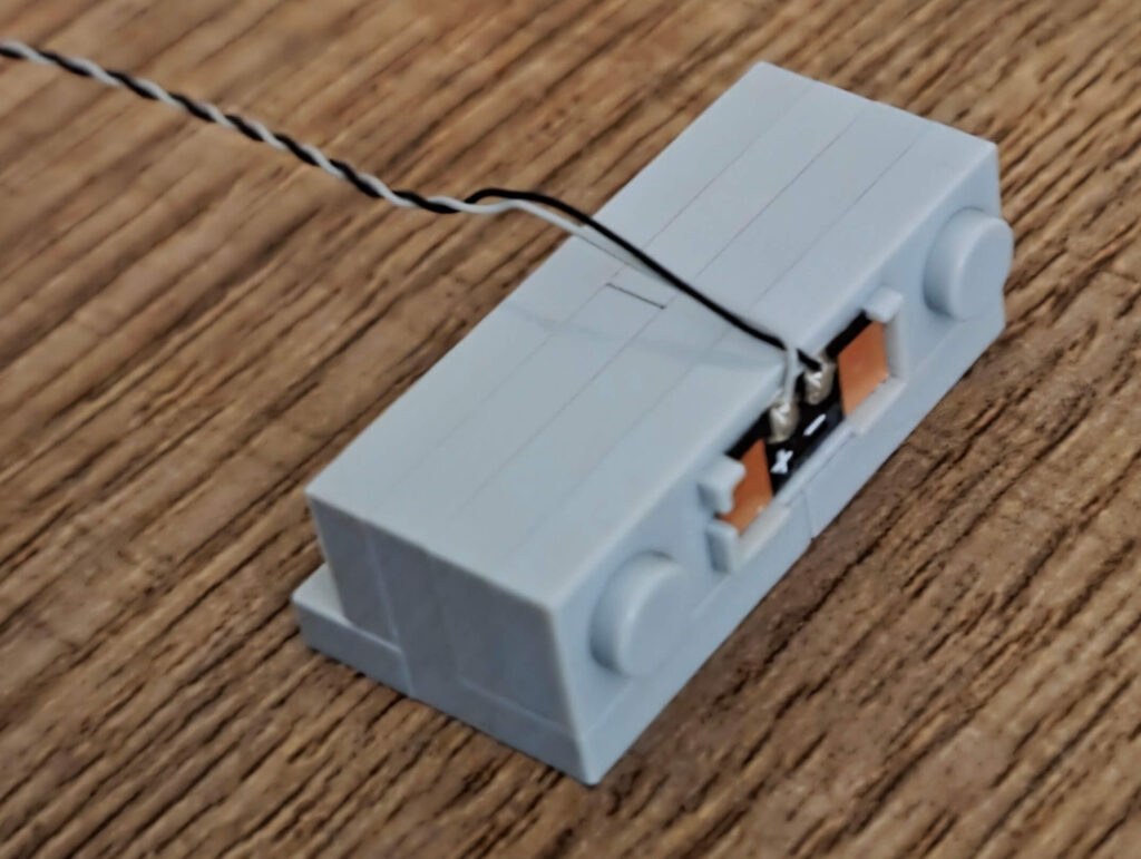
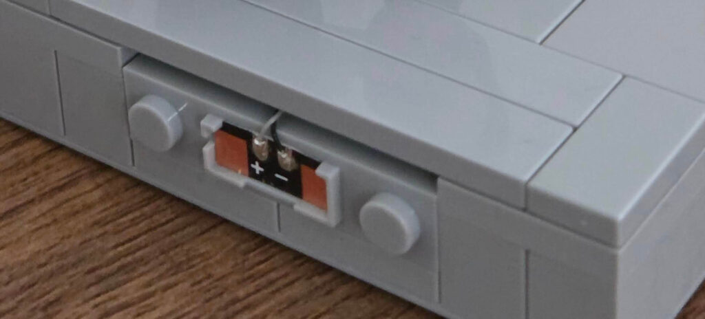
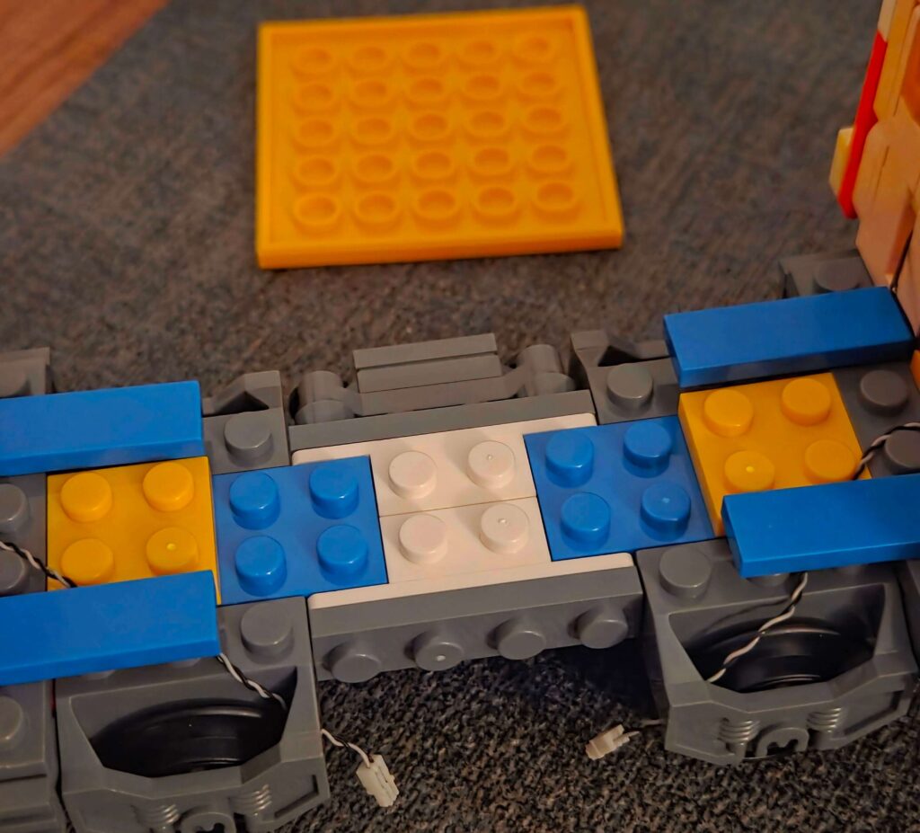
The Plan: Instead of loose wires dangling off the side, we are installing wireless power connectors on the edge of the MILS plate.
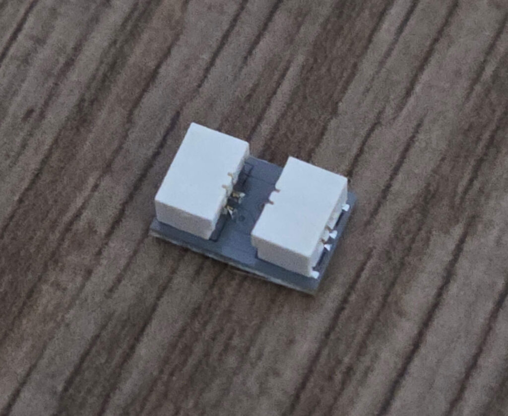
I needed two wireless connectors (one for the left side, one for the right). These come in pairs: one with studs, one with anti-studs.
Step 1: The Setup I decided on a front-on view: Station on the Left, Tram on the Right.
First, I stripped out the old battery box connection entirely. We don’t need it anymore. We are going mains power now.
Step 2: Building the Connector Mount I built the mount using the method seen in newer Lumibricks sets:
- 1x Wireless Connector Plate
- 2x 1×4 Plate
- 2x Bracket
Step 3: Embedding the Connector I placed this connector at the back edge of the MILS plate, about 2 studs down from the corner.
- Important Note: Newer Lumibricks “Town Life” sets place their connectors above the baseplate (edge-to-edge). Because my entire city is MILS plated, I prefer to embed mine inside the MILS layer for a flush finish.
- Compatibility Tip: If you are connecting this to official sets that aren’t MILS plated, you might need to build a small “electrical cabinet” or trash area to hide the height difference of the connector.
A Note on Tiling the Pavement: When covering the pavement back up, you will notice that placing a plate and a tile directly over the wireless casing doesn’t fit. Unfortunately, “brick maths” means the casing sits a fraction of a millimetre too high.
The Fix: Omit the underlying plate in that specific spot and just use a larger tile to bridge the gap. It will leave a tiny vertical space underneath, but this is necessary to keep your sidewalk perfectly level. It also keeps that wire from pinching.
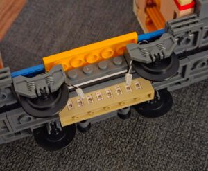
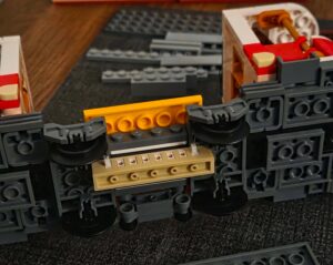
Step 4: Wiring the Station Side I plugged the wireless connector cable into a 6-port Expansion Board hidden inside the MILS base. This board will act as the “Main Hub” for this plate.
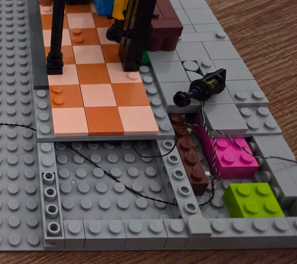
Step 5: Wiring the Track Side (The Tricky Bit) Getting power to the other side was harder because the tram track is in the way.
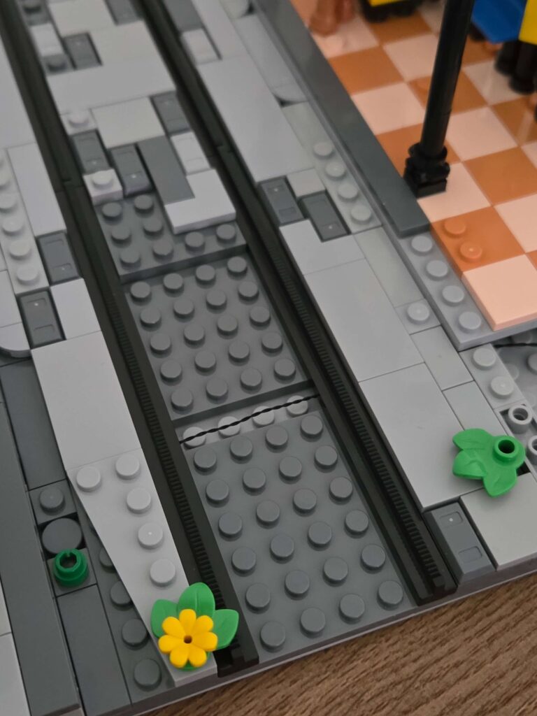
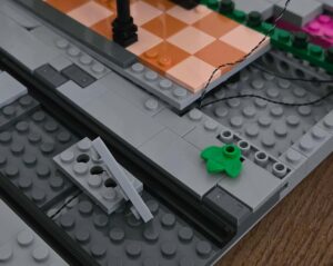
1. I removed the track and the plates underneath it.
2. I removed the large plate at the back of the build and re-plated it to create a 1 stud gap 7 studs in.
This creates a “tunnel” to thread the wire through so the track doesn’t pinch the cable when you put it back.
I installed the second wireless connector on the opposite side and threaded the wire through our new “tunnel”. You will notice I opened up a 1-stud pathway on either side to ensure the wires have enough room to pass through without being pinched.
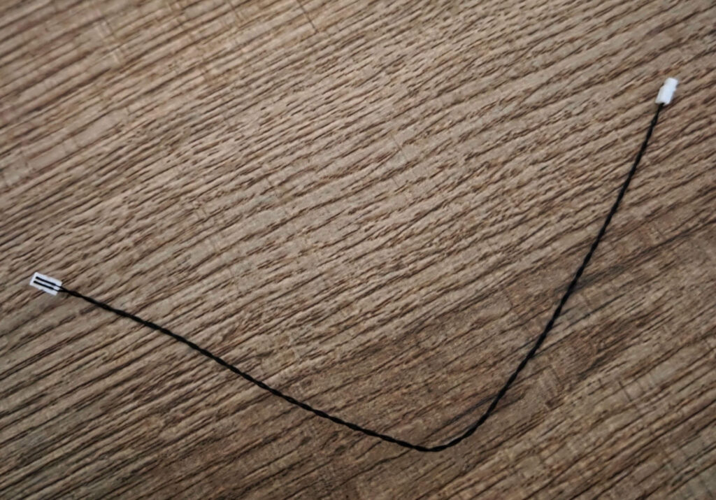
Step 6: Linking it all up Depending on the length of your wires, you might need an extension cable.
- My Method: I used a 30cm extension cable and one of the spare 2-pin adapters that came with the Tram set (do not throw these away, they are gold dust!).
I plugged everything into the main Expansion Board. Now, power flows from the left wall, through the hub, and out to the right wall.
Phase 3: The “Track Power” Mod
The Challenge: Getting power into the tram without an ugly wire trailing out the back. The Solution: Embed a wireless contact point into the track rails, and a receiver under the tram.
Part A: The Track
I needed another pair of wireless connectors.
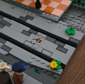
- I lifted the tiles between the track rails to access our cable tunnel.
- I placed a Wireless Connector Plate directly between the rails, sitting just above the tunnel.
- I threaded the wire down using a plate with holes and plugged it into our main Expansion Board.
Part B: The Tram Undercarriage
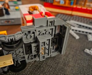
This is the most complex part of the mod. We need to reroute the power from the roof to the chassis.
- Disassemble: Remove the tram carriage body. Locate the two power cables that plug into the side adapter. Unplug them so they hang loose.
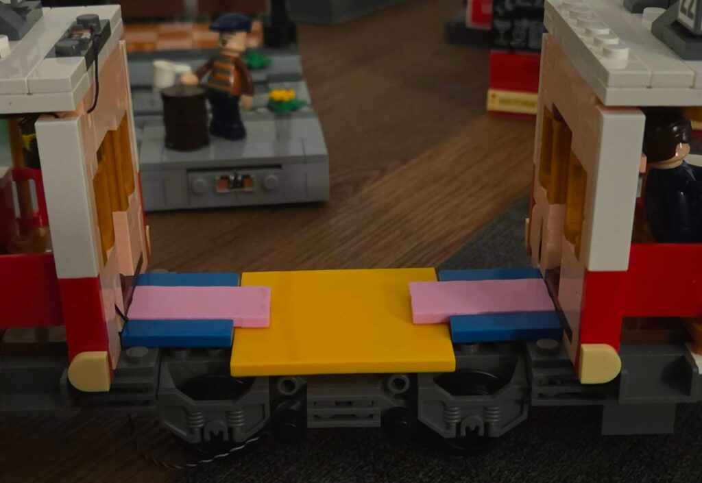
- Strip the Base: Remove the pink tiles, the large yellow plate, and the two blue 1×4 tiles on one side. This opens a path to thread cables downwards.
- Reroute: Thread the dangling power cables down through the chassis.
- Warning: Be gentle! These wires are thin. Do not pinch or pull them too hard.
- Install the Receiver:
- I attached a small Expansion Board to the underside of the tram.
- I plugged the two tram power cables into this board.
- Mount the Wireless Plate:
- I built a small “padding” section using plates to get the correct height.
- I attached the Wireless Connector Plate to this padding.
- I plugged it into the expansion board.
- Reassemble: Put the blue, yellow, and pink plates back. Tidy up any loose wires. The wireless connector should now sit flush with the bottom of the tram.
The Final Test
- Remove the battery box from the tram roof (you don’t need it anymore!).
- Place the tram on the track, lining up the connector under the tram with the connector on the track.
- Push down gently. You should feel the magnets “click” or the studs seat.
- Connect your MILS plate to a USB power bank (or another powered building).
The Result: The lights flicker to life. The tram is now powered directly from the ground – no batteries required! The tram baseplate is now getting its power from the Street Fusion set beside it!
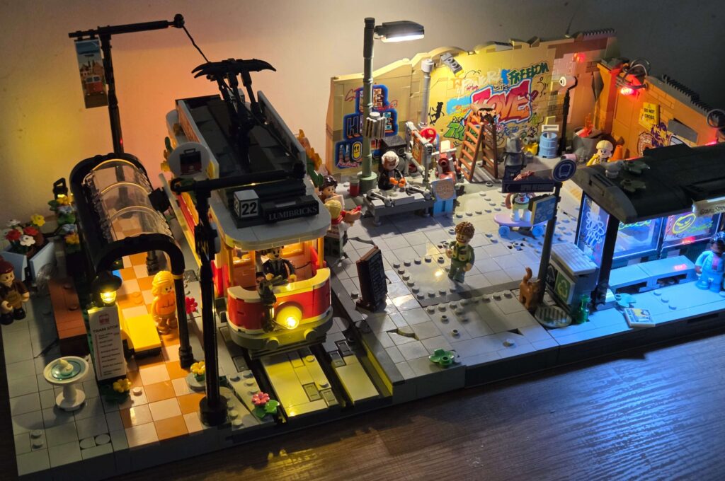
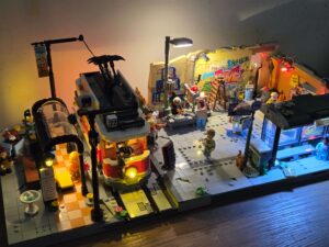
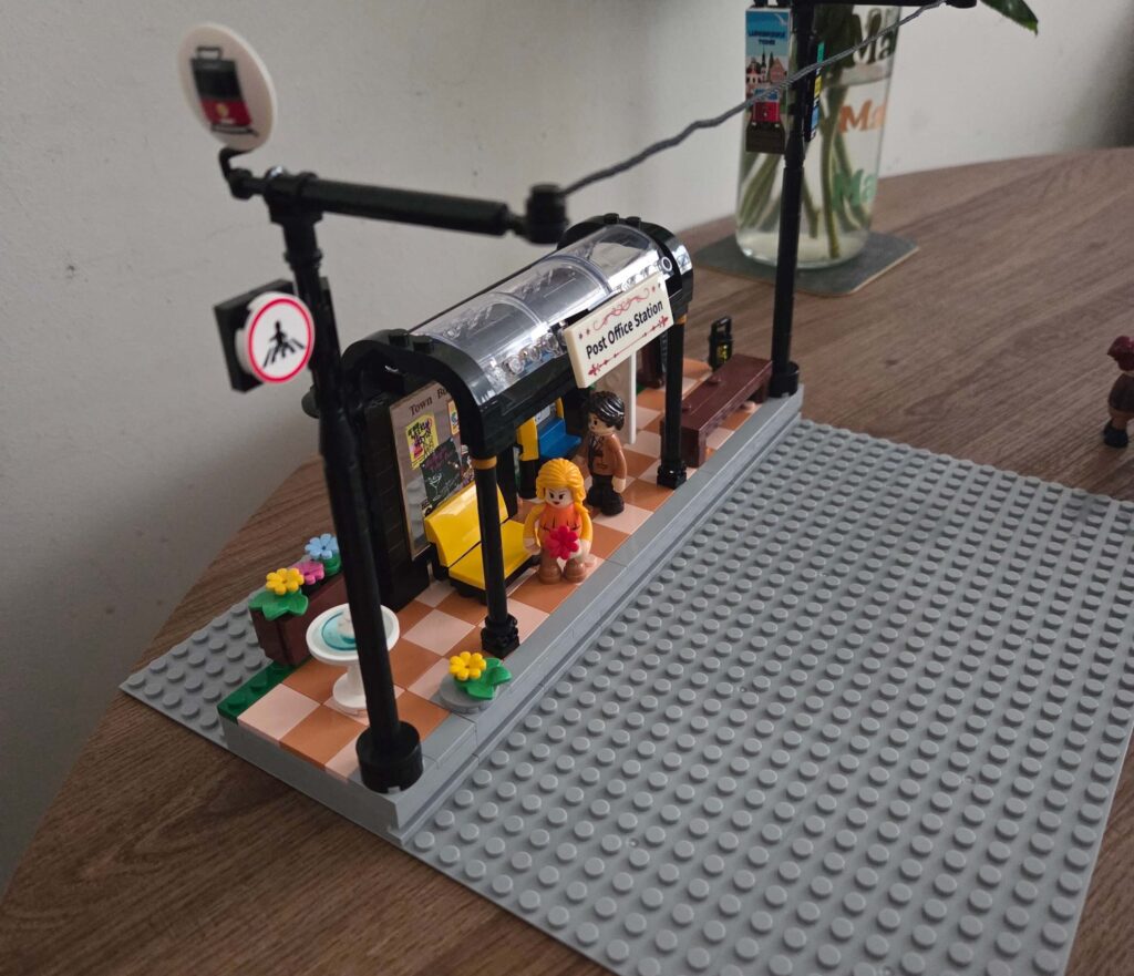
Phase 4: Adding Life & Details (The Fun Part)
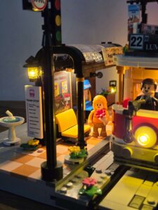
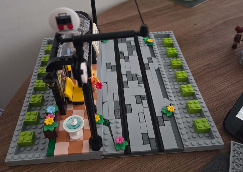
One of the biggest benefits of moving this set onto a 32×32 MOC plate is the freedom to add detail. The original footprint was cramped, but with the extra 6 studs of pavement, the scene can finally breathe.
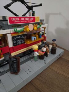
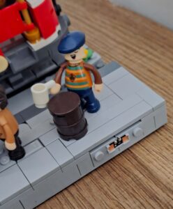
- The “Pub Tram” Vibe: Since the tram has a bar inside, I leaned into that theme. I placed a couple of beer kegs on the pavement to act as makeshift standing tables, adding a few minifigures enjoying drinks from the night tram service. I even moved the menu board nearby so customers can see what’s on tap.
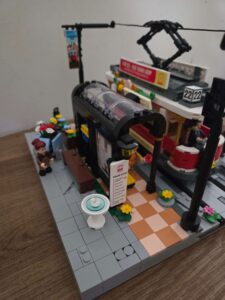
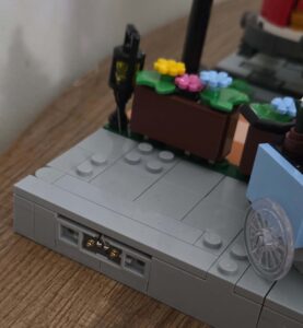
- Fountain Safety: I moved the water fountain away from the station entrance and slightly to the side. In the original build, it was a bit of a trip hazard! Now, minifigures can actually walk into the station without injuring themselves.
- Signage: I relocated the printed Tram Stop sign to the front of the station. It was hidden around the back in the original instructions, which seemed a shame because I love the print showing all the different locations. Now it’s front and centre where it belongs.
- Street Vendors: The flower cart found a perfect home on the expanded side pavement, giving the owner plenty of space to sell bouquets without blocking commuters.
All in all, the extra space has benefited the display massively. It doesn’t just look like a model anymore; it looks like a living, breathing slice of the city.